Tank wall consistency
Deep features, corners and long flow paths can create uneven wall thickness or local weakness.

Engineering Case Study
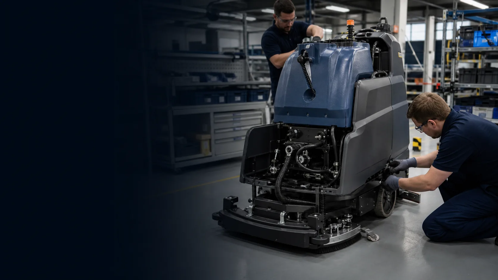
How a hollow tank, fabricated chassis, wheels, pumps and service-access components can be developed as one controlled cleaning-equipment system.
01 / Project Brief
This brief makes the relationship between application, process, material, buyer input and evidence clear before the detailed engineering narrative.
02 / Project Background
The project begins with a cleaning-equipment concept that combines a hollow liquid tank, structural chassis, wheels, pumps, hoses, covers and service parts. Tank geometry influences machine stability, drainage and access, while chassis geometry determines load transfer and assembly sequence.
A tank-only quotation would not resolve insert pull-out, mounting datums, wheel clearance or the relationship between molded shrinkage and fabricated brackets. Pauline's engineering review therefore connects rotational tooling with chassis fabrication and pilot assembly.
The buyer receives a staged route that defines what can be proven with a prototype, what must wait for production tooling, and which dimensions and functions require approved evidence.
03 / The Challenge
Deep features, corners and long flow paths can create uneven wall thickness or local weakness.
Molded-in inserts and brackets must carry service loads without distorting the tank.
Low points, ports and internal geometry must support emptying, rinsing and maintenance.
Fabricated datums must accommodate molding variation while keeping wheels, pumps and covers aligned.
Hoses, fasteners and service components need a repeatable build sequence with accessible inspection points.
04 / Engineering Analysis and DFM
Every review item should identify the question, responsible owner and evidence needed before tooling, production or assembly moves forward.
| Review area | Engineering question | Release evidence |
|---|---|---|
| Tank geometry | Review radii, draft, split line, wall distribution and demolding direction. | Rotational molding DFM and tooling concept |
| Ports and inserts | Confirm load, sealing face, access and insert retention method. | Insert map and pull/torque check plan |
| Chassis | Define datums, weld sequence, coating allowance and adjustable interfaces. | Fabrication drawing and inspection fixture |
| Fluid route | Check hose routing, drainage, pump access and leak-risk interfaces. | Assembly drawing and functional test scope |
| Serviceability | Confirm replaceable components and tool access for field maintenance. | Pilot-build issue list and closure record |
05 / Selected Solution
Use the tank mounting plane and chassis fixture as controlled reference systems, keep critical ports and inserts tied to those datums, and validate pump, hose and wheel clearances in a pilot assembly before repeat production. Molding and fabrication changes are closed against the same assembly record.
The final route remains project-specific. Cost, MOQ and lead time become reliable only after materials, files, component responsibility, acceptance criteria and change ownership are confirmed.
Solution controls
06 / Manufacturing Route
Use, CAD, sample, components, volumes and open decisions.
Map architecture, interfaces, scope and evidence.
Test the highest-risk fit, access or functional assumptions.
Close process, tolerance, finish and assembly risks.
Release tools and fixtures against controlled files.
Produce parts through approved process plans.
Validate bought-out parts and complete-product interfaces.
Control changes, packing, records and delivery.
Review process fit, interfaces, evidence, MOQ, lead time and buyer inputs for this project stage.
Review related service →Review process fit, interfaces, evidence, MOQ, lead time and buyer inputs for this project stage.
Review related service →Review process fit, interfaces, evidence, MOQ, lead time and buyer inputs for this project stage.
Review related service →Review process fit, interfaces, evidence, MOQ, lead time and buyer inputs for this project stage.
Review related service →07 / Quality and Validation
A credible project record names the check, method, sample or record and approval owner. Generic quality claims do not replace project-specific acceptance criteria.
Wall distribution, port location, insert position, visual limits and leak check
Datum location, weld quality, flatness, coating and wheel-mount geometry
Hose routing, pump access, fastener control, wheel clearance and service reach
Tool trial report, dimensional check, leak record and pilot-build issue closure
08 / Project Result
These release outcomes describe the intended evidence structure.
Review Pauline quality management →Evidence-led outcome framework
09 / Production Evidence
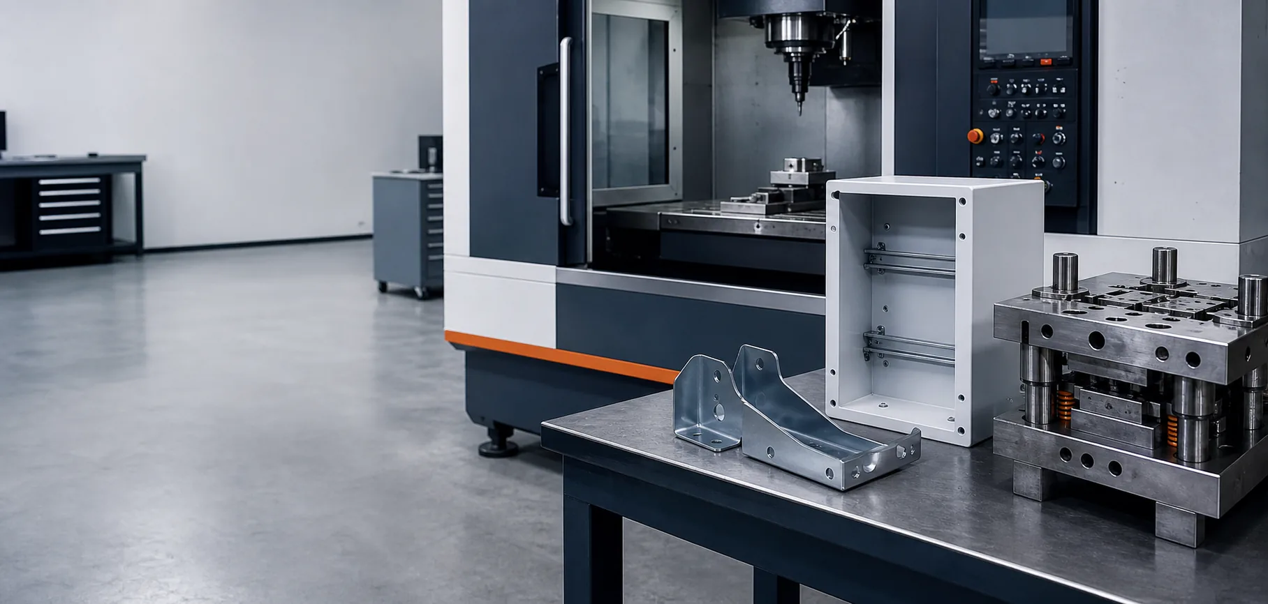
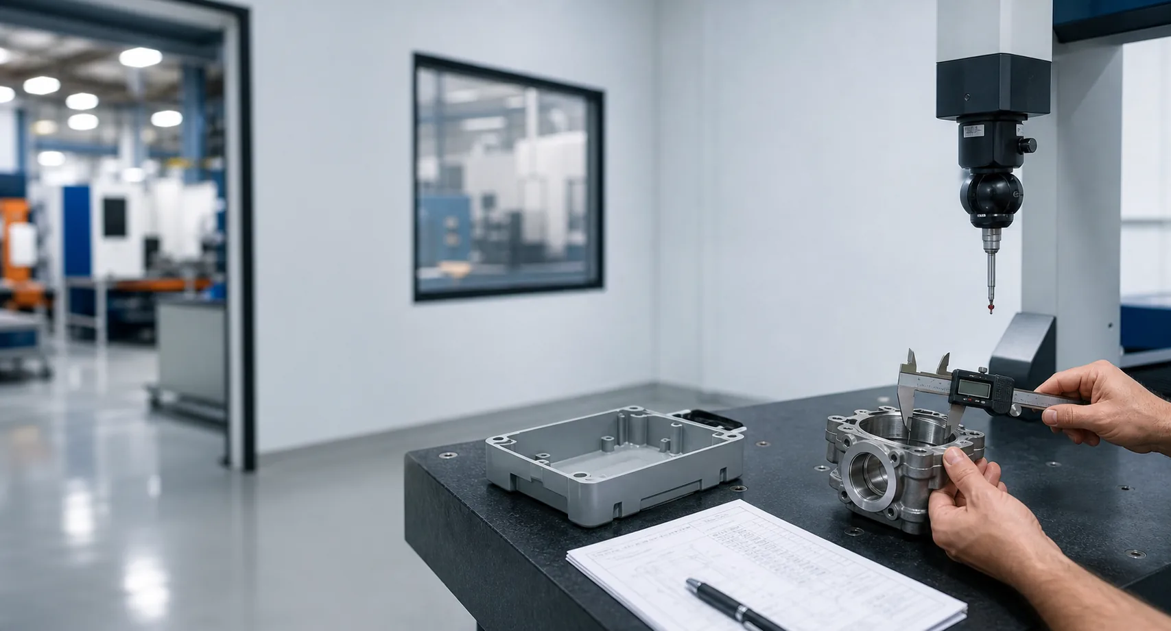
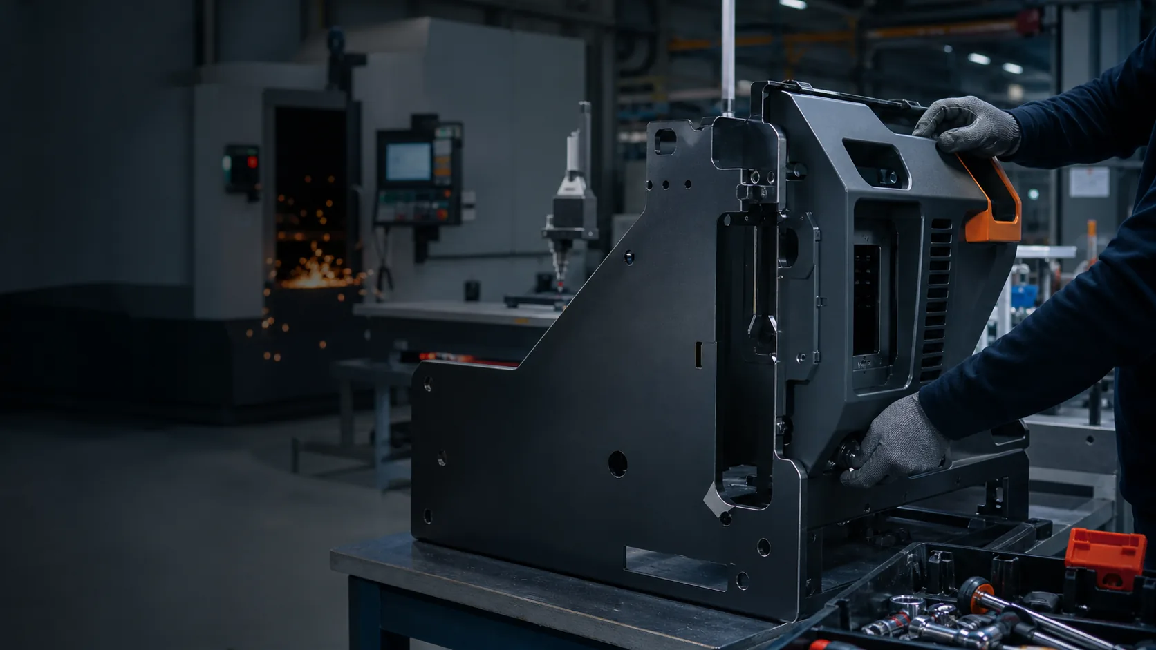
10 / Engineering Lessons
For cleaning equipment, the most expensive problems often appear where the molded tank meets the chassis, pump and service hardware. Those interfaces should be validated together, not after separate parts arrive.
This conclusion should remain tied to the documented engineering route and should be revised when real project evidence changes the lesson.
11 / Buyer FAQ
LLDPE and HDPE are common starting points, but the final grade depends on chemicals, impact, temperature, UV exposure, stiffness and cleaning requirements.
Tool design, charge weight, heating cycle, rotation ratio and part geometry influence distribution; checks should be defined at risk areas.
Yes, with an agreed scope for fabricated parts, bought-out components, assembly steps and functional checks.
Provide volume, fluid type, capacity, CAD or sample, load cases, components, finish, target market and required validation.
14 / Request a Project Review
Share CAD or drawings, a sample where available, product use, material and finish direction, target quantity, bought-out components, destination, timing and the technical or commercial decision you need to make.