Thermal path
Vent, fan, heat-sink and internal clearance decisions affect tooling and enclosure layout.


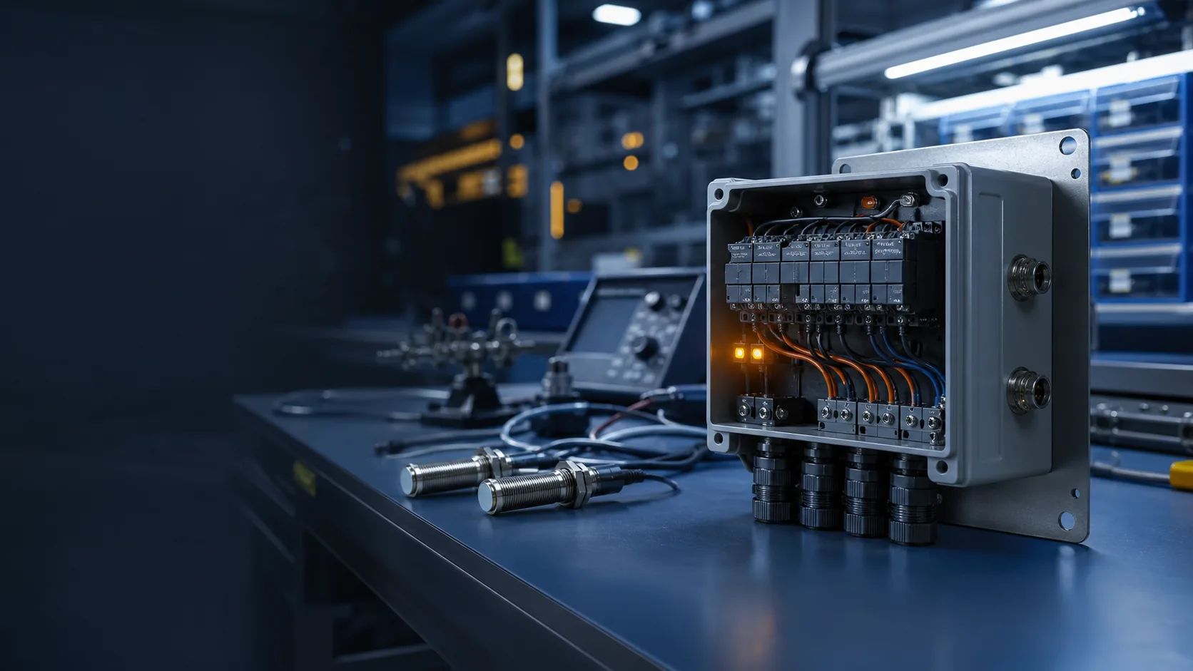
Engineering Case Study
An engineering case structure for balancing thermal management, connector access, cable routing, appearance and multi-process enclosure production.
01 / Project Brief
This brief makes the relationship between application, process, material, buyer input and evidence clear before the detailed engineering narrative.
02 / Project Background
The product houses control electronics, power components, connectors and service hardware in a mechanical enclosure that may use molded covers, machined heat-transfer features and fabricated internal frames.
The main sourcing risk is not any single process. It is whether vent paths, connectors, bosses, brackets, door clearances and cable routes still work after molding, machining, coating and assembly tolerances are applied.
Pauline coordinates the mechanical product definition, separates buyer-owned electrical validation from manufacturing checks, and creates release evidence for the enclosure and its interfaces.
03 / The Challenge
Vent, fan, heat-sink and internal clearance decisions affect tooling and enclosure layout.
Cutouts, molded openings and internal brackets must locate mating components without forced assembly.
Material, coating masks and contact surfaces must match the buyer's engineering specification.
Panels and fasteners should support installation and maintenance without disturbing critical components.
Molding, machining, bending and coating variation must be absorbed by a deliberate datum scheme.
04 / Engineering Analysis and DFM
Every review item should identify the question, responsible owner and evidence needed before tooling, production or assembly moves forward.
| Review area | Engineering question | Release evidence |
|---|---|---|
| Enclosure architecture | Map load paths, heat paths, access panels and component ownership. | Controlled architecture and interface drawing |
| Molded parts | Review walls, ribs, bosses, inserts, vents, gate and ejection. | Molding DFM and tool-release record |
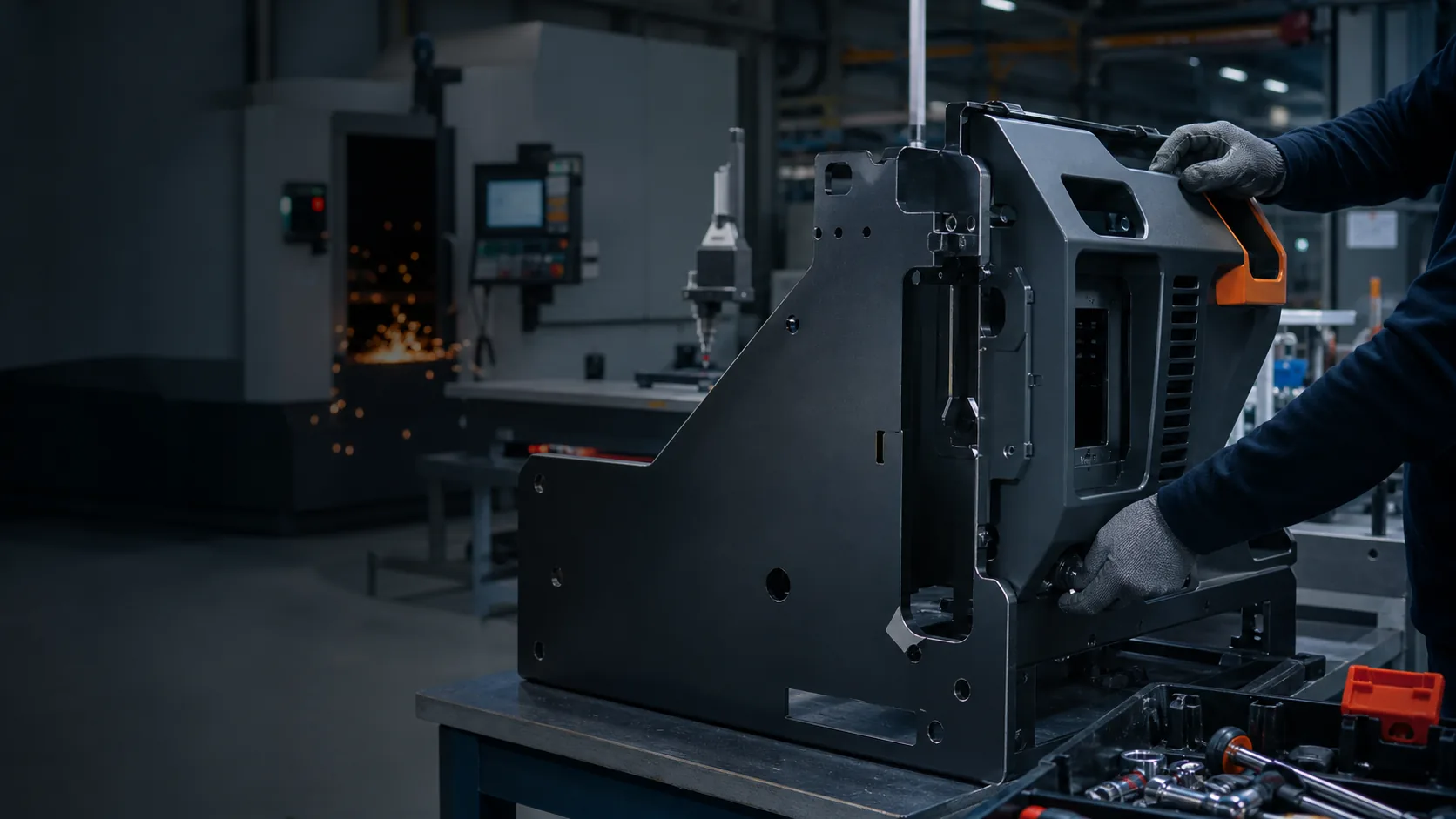
| Metal parts | Review cutouts, bends, PEM hardware, masks and coating allowance. | Fabrication drawing and finish specification |
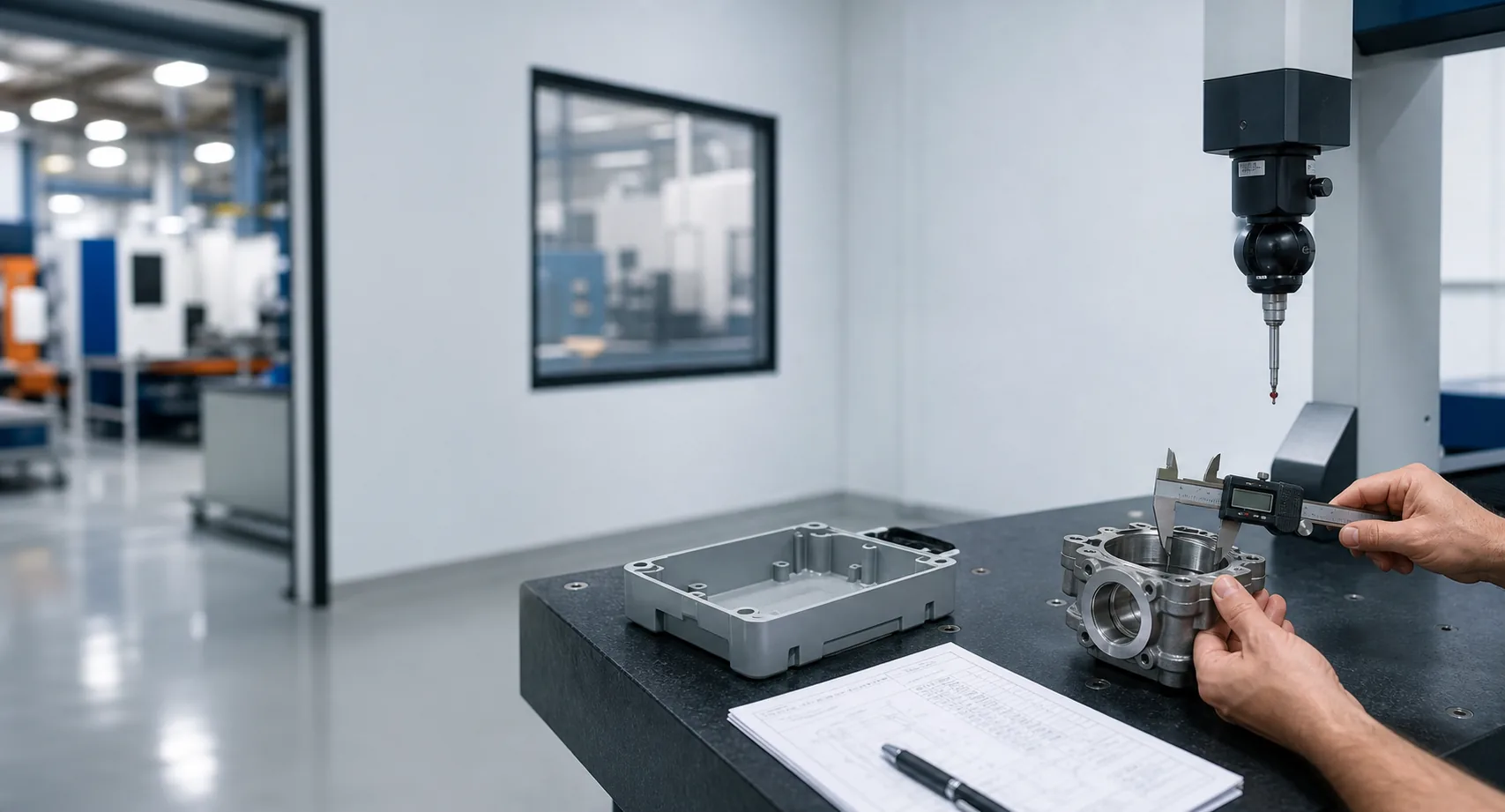
| Component fit | Check connectors, PCBs, fans and customer-specified hardware against datums. | Measured trial assembly and issue closure |
| Validation boundary | Separate manufacturing checks from buyer-owned electrical and compliance tests. | Responsibility matrix and approval plan |
05 / Selected Solution
Define enclosure datums around the component and connector interfaces, provide controlled adjustment where process variation requires it, and validate the complete mechanical build before recurring production. Coating masks, grounding surfaces and appearance limits are documented rather than left to supplier interpretation.
The final route remains project-specific. Cost, MOQ and lead time become reliable only after materials, files, component responsibility, acceptance criteria and change ownership are confirmed.
Solution controls
06 / Manufacturing Route
Use, CAD, sample, components, volumes and open decisions.
Map architecture, interfaces, scope and evidence.
Test the highest-risk fit, access or functional assumptions.
Close process, tolerance, finish and assembly risks.
Release tools and fixtures against controlled files.
Produce parts through approved process plans.
Validate bought-out parts and complete-product interfaces.
Control changes, packing, records and delivery.
Review process fit, interfaces, evidence, MOQ, lead time and buyer inputs for this project stage.
Review related service →Review process fit, interfaces, evidence, MOQ, lead time and buyer inputs for this project stage.
Review related service →Review process fit, interfaces, evidence, MOQ, lead time and buyer inputs for this project stage.
Review related service →Review process fit, interfaces, evidence, MOQ, lead time and buyer inputs for this project stage.
Review related service →07 / Quality and Validation
A credible project record names the check, method, sample or record and approval owner. Generic quality claims do not replace project-specific acceptance criteria.
Connector and PCB locations, panel flatness, boss and insert positions
Component clearance, cable access, door movement and fastener engagement
Texture, color, mask location, grounding contact and cosmetic limits
DFM approval, first article, trial assembly and buyer-defined functional boundary
08 / Project Result
These release outcomes describe the intended evidence structure.
Review Pauline quality management →Evidence-led outcome framework
09 / Production Evidence
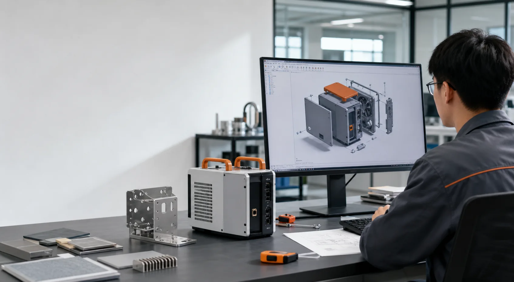
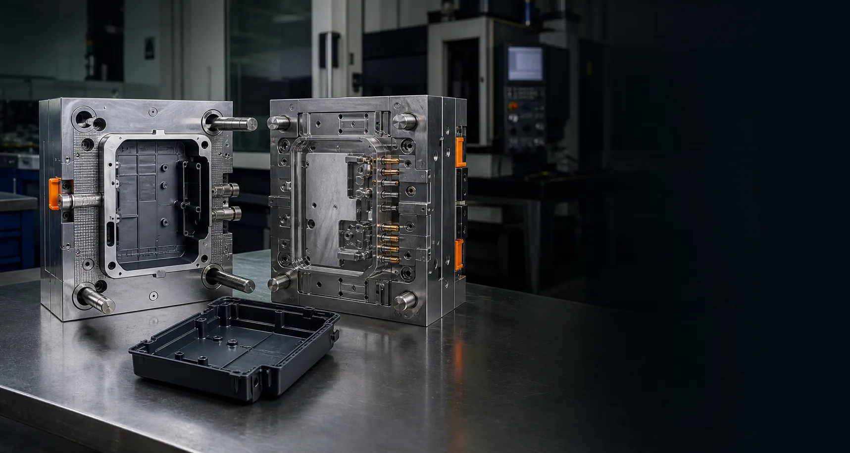
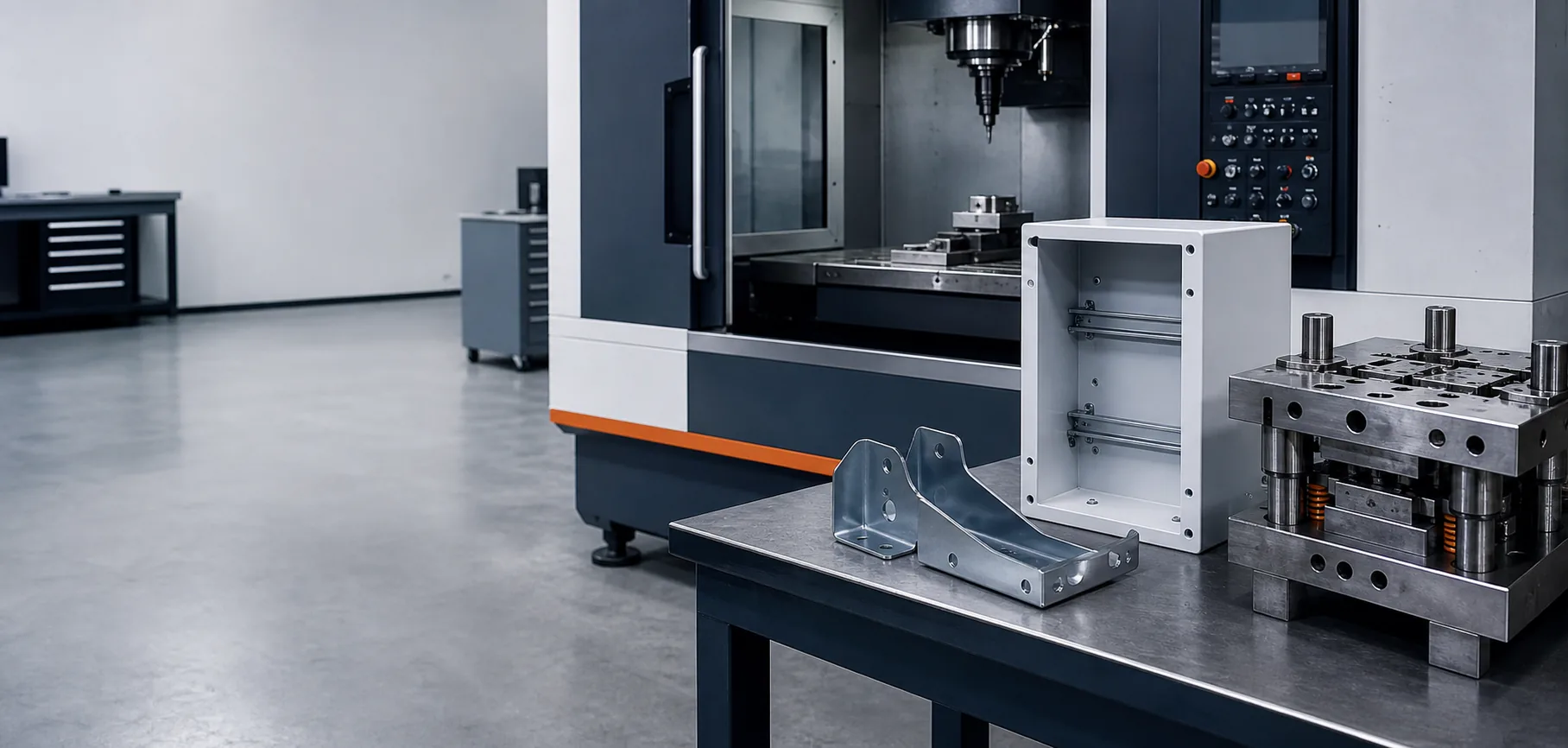
10 / Engineering Lessons
An automation enclosure should be designed around components, connectors, heat and service access before its outer surfaces are frozen. Cosmetic geometry alone is not a manufacturable product architecture.
This conclusion should remain tied to the documented engineering route and should be revised when real project evidence changes the lesson.
11 / Buyer FAQ
Yes. Provide component models, keep-out zones, connectors, thermal constraints, grounding requirements and the buyer's validation responsibility.
Sheet metal, CNC machining, vacuum casting or soft tooling may be suitable; geometry, appearance, volume and investment determine the route.
They can be specified and inspected when contact areas, coating system and acceptance method are defined.
Only if certification is explicitly included and performed by an agreed qualified party. Mechanical manufacturing evidence does not replace product certification.
14 / Request a Project Review
Share CAD or drawings, a sample where available, product use, material and finish direction, target quantity, bought-out components, destination, timing and the technical or commercial decision you need to make.