Wet-material selection
Resin, seals and purchased components must match fluid, temperature and cleaning conditions.

Engineering Case Study
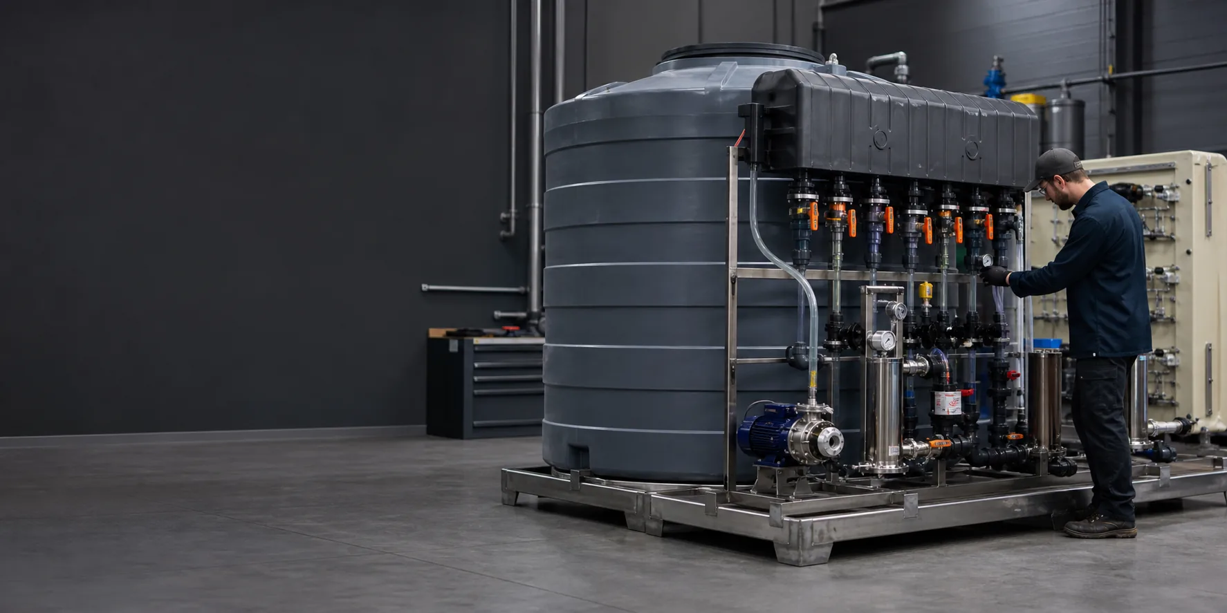
How tank geometry, pump and valve interfaces, wet materials, service access and final assembly can be coordinated before tooling and supplier commitments.
01 / Project Brief
This brief makes the relationship between application, process, material, buyer input and evidence clear before the detailed engineering narrative.
02 / Project Background
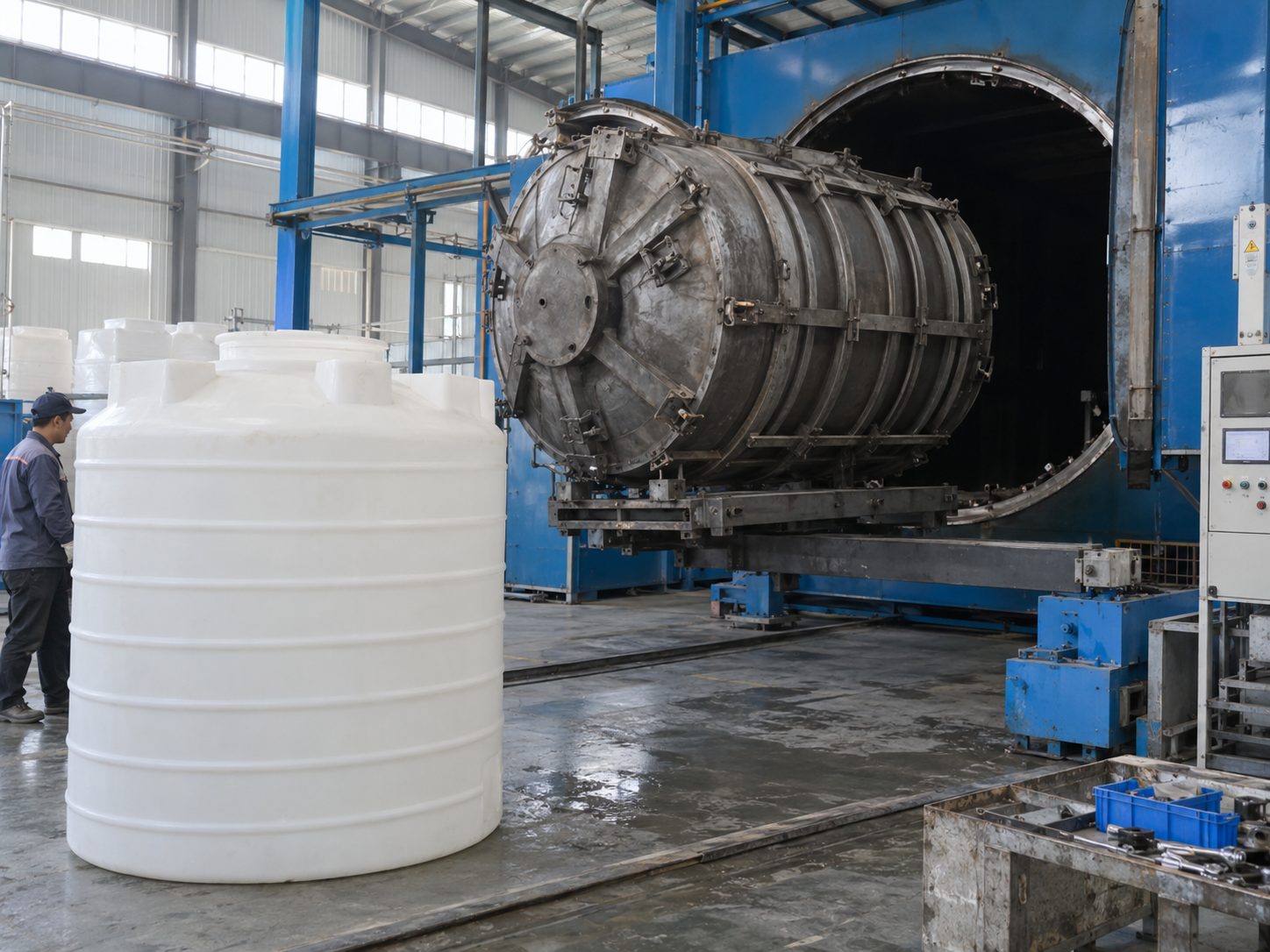
The product combines a fluid reservoir or pressure-free tank, molded housings, pumps, valves, tubing, seals, brackets, covers and customer-facing controls.
Material compatibility, port position and service access drive the design. A visually acceptable housing is not enough if pumps cannot be replaced, hoses kink, threaded inserts leak or wet materials are not documented.
Pauline's route starts by defining the fluid path and component responsibility, then links product DFM, tooling, sourcing and assembly to the same controlled interface map.
03 / The Challenge
Resin, seals and purchased components must match fluid, temperature and cleaning conditions.
Locations, sealing faces and thread standards must align with pumps, valves and regional fittings.
Hose routing, clamps, inserts and assembly torque influence the complete fluid path.
Filters, pumps, tubes and valves need replacement space and clear work instructions.
Bought-out fluid components require approved sources, incoming checks and substitution control.
04 / Engineering Analysis and DFM
Every review item should identify the question, responsible owner and evidence needed before tooling, production or assembly moves forward.
| Review area | Engineering question | Release evidence |
|---|---|---|
| Fluid architecture | Map wet materials, pressure boundary, drainage and service points. | Fluid-path and responsibility diagram |
| Molded components | Review wall, ribs, bosses, inserts, ports, gate and shrinkage. | DFM and tooling release |
| Purchased parts | Confirm specifications, regional standards and acceptable alternatives. | Approved BOM and incoming criteria |
| Assembly | Check hose bend radius, clamp access, torque and leak-risk points. | Work instruction and leak-check plan |
| Validation | Define dimensional, leak, flow and buyer-owned performance tests. | Test boundary and approval record |
05 / Selected Solution
Use the fluid-path diagram as the master interface document, validate pump, valve, hose and housing clearances in a pilot build, and control wet materials and purchased components through the approved BOM. Leak checks are tied to defined joints and assembly records.
The final route remains project-specific. Cost, MOQ and lead time become reliable only after materials, files, component responsibility, acceptance criteria and change ownership are confirmed.
Solution controls
06 / Manufacturing Route
Use, CAD, sample, components, volumes and open decisions.
Map architecture, interfaces, scope and evidence.
Test the highest-risk fit, access or functional assumptions.
Close process, tolerance, finish and assembly risks.
Release tools and fixtures against controlled files.
Produce parts through approved process plans.
Validate bought-out parts and complete-product interfaces.
Control changes, packing, records and delivery.
Review process fit, interfaces, evidence, MOQ, lead time and buyer inputs for this project stage.
Review related service →Review process fit, interfaces, evidence, MOQ, lead time and buyer inputs for this project stage.
Review related service →Review process fit, interfaces, evidence, MOQ, lead time and buyer inputs for this project stage.
Review related service →Review process fit, interfaces, evidence, MOQ, lead time and buyer inputs for this project stage.
Review related service →07 / Quality and Validation
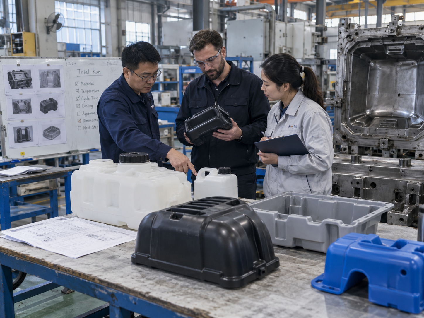
A credible project record names the check, method, sample or record and approval owner. Generic quality claims do not replace project-specific acceptance criteria.
Resin grade, wet-material declarations and purchased component identity
Port position, threads, sealing faces, brackets and mating dimensions
Assembly fit, service access and project-defined leak or flow checks
DFM, sample approval, incoming inspection, assembly and test records
08 / Project Result
These release outcomes describe the intended evidence structure.
Review Pauline quality management →Evidence-led outcome framework
09 / Production Evidence
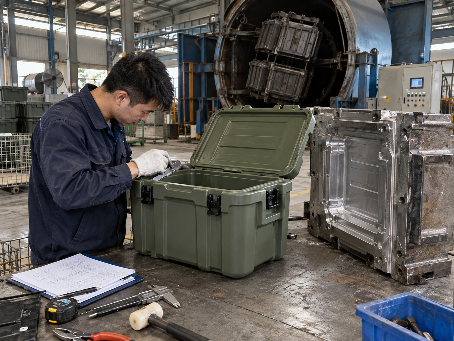
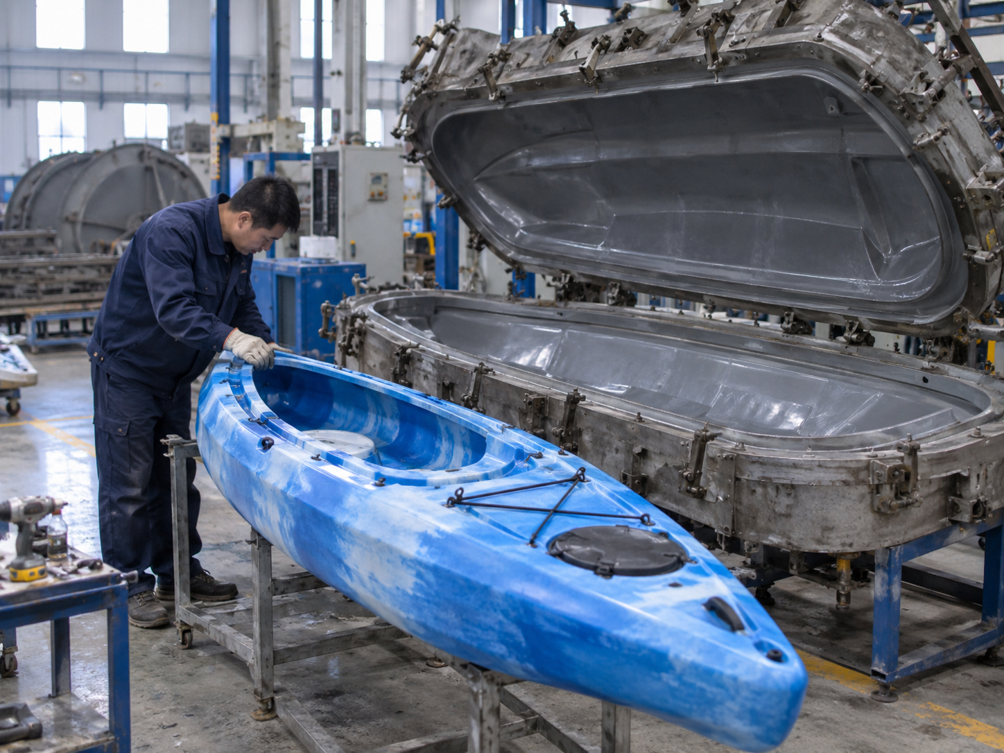
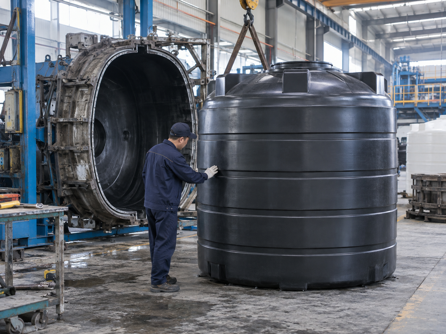
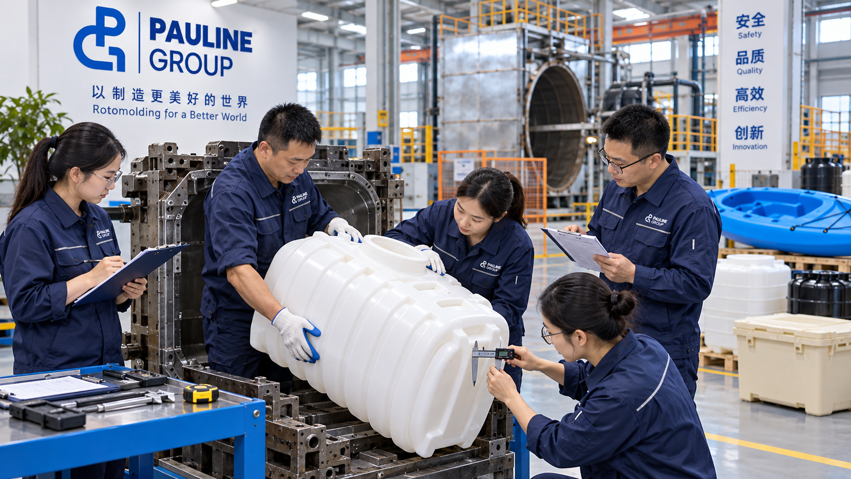

10 / Engineering Lessons
Fluid-system reliability is built at the interfaces. Resin selection matters, but port geometry, seals, hose routing, assembly torque and service access determine whether the complete product can be produced and maintained consistently.
This conclusion should remain tied to the documented engineering route and should be revised when real project evidence changes the lesson.
11 / Buyer FAQ
PP, HDPE, ABS, PC and engineering resins may be suitable. Fluid chemistry, temperature, pressure, stiffness, appearance and compliance requirements determine the grade.
Yes, using buyer-approved specifications, supplier qualification, incoming criteria and substitution control.
The buyer and Pauline should identify the pressure or operating condition, duration, acceptable leakage, test fixtures and record format.
Yes. Provide samples, CAD, BOM, failure history, volumes and target changes so the engineering team can protect critical functions while reviewing cost.
14 / Request a Project Review
Share CAD or drawings, a sample where available, product use, material and finish direction, target quantity, bought-out components, destination, timing and the technical or commercial decision you need to make.